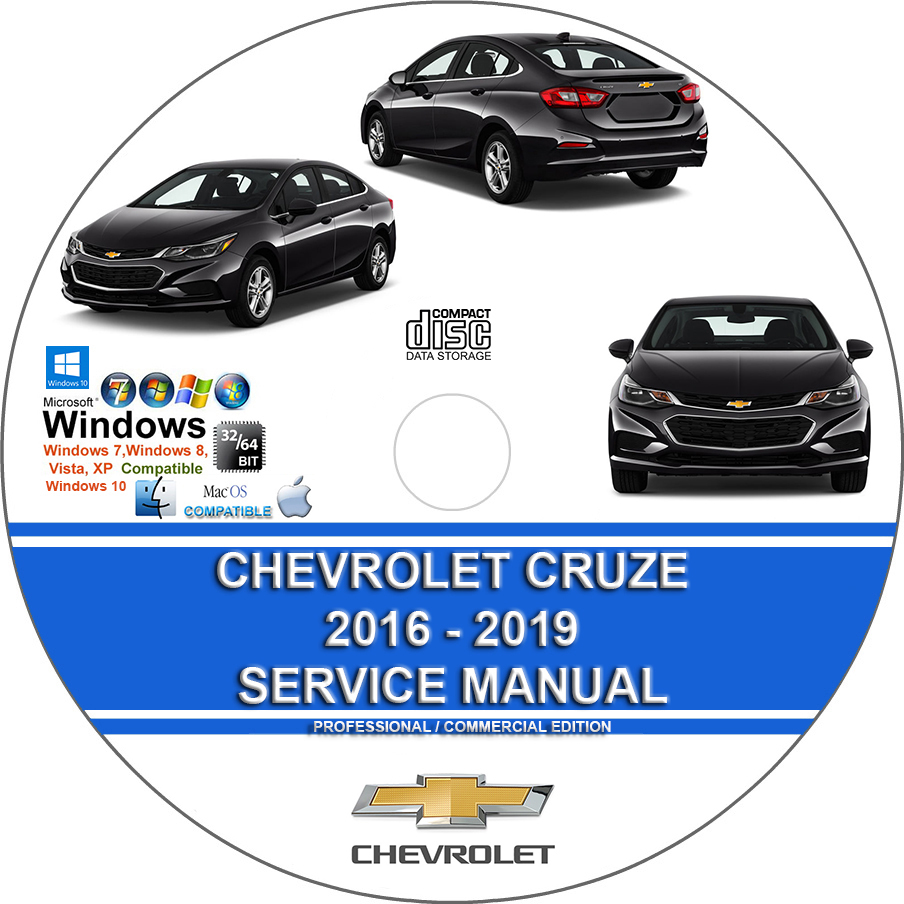
Chevrolet Cruze 2016 2017 2018 Factory Service Repair Manual + Wiring Diagrams
$37.00 – $46.00Price range: $37.00 through $46.00
Chevrolet Cruze 2016 2017 2018 Factory Service Repair Manual + Wiring Diagrams
You can download this or I can ship it to you.
Loaded with Hi Resolution illustrations, instructions, photos, and diagrams, complete to service and repair your CHEVROLET.
11 900 Pages
Chevrolet Cruze 2016 2017 2018 Factory Service Repair Manual + Wiring Diagrams
Loaded with illustrations, instructions, photos, and diagrams, complete to service and repair your Chevy.
11 900 Pages
You can download this or I can ship it to you.
MODEL YEAR:
2016 2017 2018 2019
ENGINE:
1.4L
1.6L
MANUAL COVERS:
- General Information
- Antilock Brake System
- Automatic Transmission – 6T35 (MNU) – Component Locator
- Automatic Transmission – 6T35 (MNU) – Description and Operation
- Automatic Transmission – 6T35 (MNU) – Diagnostic Information and Procedures
- Automatic Transmission – 6T35 (MNU) – Repair Instructions
- Automatic Transmission – 6T35 (MNU) – Schematic and Routing Diagrams
- Automatic Transmission – 6T35 (MNU) – Special Tools and Equipment
- Automatic Transmission – 6T35 (MNU) – Specifications
- Automatic Transmission – 9T50 (M3D) – Component Locator
- Automatic Transmission – 9T50 (M3D) – Description and Operation
- Automatic Transmission – 9T50 (M3D) – Diagnostic Information and Procedures
- Automatic Transmission – 9T50 (M3D) – Repair Instructions
- Automatic Transmission – 9T50 (M3D) – Schematic and Routing Diagrams
- Automatic Transmission – 9T50 (M3D) – Special Tools and Equipment
- Automatic Transmission – 9T50 (M3D) – Specifications
- Bolted Exterior Body Panels and Closures
- Bumpers and Fascias
- Cellular, Entertainment, and Navigation
- Instrument Panel/Center Console Component Views
- Clutch
- Collision Repair
- Component Connector And Inline Harness Connector End Views
- Component Connector End Views Wiring Systems
- Door Component Views Wiring Systems
- Wiring Systems Ground Views
- Cruise Control
- Dangers, Warnings, and Cautions
- Data Communications
- Wiring Systems Diagnostic Information and Procedures
- Disc Brakes
- Displays and Gauges
- ANTILOCK BRAKE SYSTEM – DTC
- Wiring Systems Component Locator – Electrical Center Identification Views
- Wiring Systems Front of Vehicle/Engine Compartment Component Views
- Engine Controls and Fuel – 1.4L (LE2) – Description and Operation
- Engine Controls and Fuel – 1.4L (LE2) – Diagnostic Information and Procedures
- Engine Controls and Fuel – 1.4L (LE2) – Repair Instructions
- Engine Controls and Fuel – 1.4L (LE2) – Schematic and Routing Diagrams
- Engine Controls and Fuel – 1.4L (LE2) – Special Tools and Equipment
- Engine Controls and Fuel – 1.4L (LE2) – Specifications
- Engine Controls and Fuel – 1.6L (LH7) Diesel – Description and Operation
- Engine Controls and Fuel – 1.6L (LH7) Diesel – Diagnostic Information and Procedures
- CRANKSHAFT POSITION – CAMSHAFT POSITION NOT PLAUSIBLE
- DTC P0407, P0408, P046E, OR P046F: EXHAUST GASRECIRCULATION COOLER COOLANT INLET TEMPERATURE SENSOR
- REDUCTANT QUALITY SENSOR CIRCUIT
- Engine Controls and Fuel – 1.6L (LH7) Diesel – Repair Instructions
- CRANKSHAFT POSITION RELUCTOR RING LEARN
- EMISSION REDUCTION FLUID SYSTEM DESCRIPTION
- Engine Controls and Fuel – 1.6L (LH7) Diesel – Schematic and Routing Diagrams
- ENGINE CONTROLS WIRING SCHEMATICS
- Engine Controls and Fuel – 1.6L (LH7) Diesel – Special Tools and Equipment
- Engine Controls and Fuel – 1.6L (LH7) Diesel – Specifications
- Engine Heating and Cooling
- Engine Mechanical – 1.4L (LE2) – Component Locator
- Cylinder Head and Components
- Drive Belt Accessory Components
- Engine Block and Components
- Engine Front Cover and Components
- Turbocharger and Components
- Water Pump and Components
- Intake Manifold and Components
- Oil Pan and Components
- Timing Chain and Components
- Engine Identification Code
- Engine Mechanical – 1.4L (LE2) – Description and Operation
- Positive Crankcase Ventilation System
- Cutaway View Of Lubrication System
- Engine Mechanical – 1.4L (LE2) – Diagnostic Information and Procedures
- ENGINE OIL PRESSURE
- Engine Mechanical – 1.4L (LE2) – Repair Instructions
- Draining Fluids and Oil Filter
- CRANKSHAFT BALANCER REMOVAL
- AUTOMATIC TRANSMISSION FLEX PLATE REMOVAL
- ENGINE FLYWHEEL REMOVAL
- TURBOCHARGER REMOVAL
- ENGINE OIL COOLER REMOVAL
- WATER PUMP REMOVAL
- THROTTLE BODY ASSEMBLY REMOVAL
- INTAKE MANIFOLD REMOVAL
- FUEL PUMP REMOVAL
- ENGINE LIFT AND SIGHT SHIELD BRACKET REMOVAL
- WATER OUTLET REMOVAL
- VACUUM PUMP REMOVAL
- IGNITION COIL REMOVAL
- FUEL RAIL AND INJECTORS REMOVAL
- CAMSHAFT COVER REMOVAL
- OIL PAN REMOVAL
- ENGINE FRONT COVER REMOVAL
- CAMSHAFT TIMING CHAIN REMOVAL
- INTAKE AND EXHAUST CAMSHAFT, BEARING CAP, AND LASH ADJUSTER REMOVAL
- Camshaft Bearings and Camshaft Removal
- Valve Rocker Arm and Lash Adjuster Removal
- CYLINDER HEAD REMOVAL
- OIL PUMP DRIVE CHAIN AND OIL PUMP REMOVAL
- Oil Pump Drive Chain and Crankshaft Sprocket Removal
- Oil Pump Assembly Removal
- CRANKSHAFT OIL DEFLECTOR REMOVAL
- LOWER CRANKCASE REMOVAL
- PISTON, CONNECTING ROD, AND BEARING REMOVAL
- CRANKSHAFT AND BEARING REMOVAL
- CYLINDER HEAD DISASSEMBLE
- Intake and Exhaust Valve Removal
- Cylinder Head Oil Gallery Plugs, Turbocharger Studs, Spark Plugs, and Engine Oil Manifold Check Valve Removal
- CYLINDER HEAD CLEANING AND INSPECTION
- Cylinder Head and Gasket Surface Cleaning and Inspection
- Valve Measurement and Reconditioning Overview
- CAMSHAFT TIMING CHAIN AND SPROCKET CLEANING AND INSPECTION
- DRIVE BELT REPLACEMENT
- ENGINE SIGHT SHIELD REPLACEMENT
- CAMSHAFT COVER REPLACEMENT
- CAMSHAFT POSITION ACTUATOR REPLACEMENT
- EXHAUST CAMSHAFT REPLACEMENT
- INTAKE CAMSHAFT REPLACEMENT
- CAMSHAFT TIMING CHAIN REPLACEMENT
- Engine Mechanical – 1.4L (LE2) – Schematic and Routing Diagrams
- Engine Mechanical – 1.4L (LE2) – Special Tools and Equipment
- VALVE STEM OIL SEAL AND VALVE SPRING REPLACEMENT
- Valve Stem Oil Seal Replacement Procedure
- CHARGE AIR BYPASS REGULATOR SOLENOID VALVE VACUUM TUBE REMOVAL
- Engine Mechanical – 1.4L (LE2) – Specifications
- Engine Mechanical – 1.6L (LH7) Diesel
- Exhaust
- Exterior Trim
- Floor Coverings and Headlinings
- Frame and Underbody
- FRONT FLOOR PANEL CARPET REPLACEMENT
- Air Conditioning Evaporator and Blower Module Drain Hose Replacement
- DRIVETRAIN AND FRONT SUSPENSION CRADLE REPLACEMENT
- Front Suspension
- HVAC Heating, Ventilation, and Air Conditioning
- Horns
- Hydraulic Brakes
- Immobilizer
- IMMOBILIZER WIRING SCHEMATICS
- Inline Harness Connector End Views
- Instrument Panel and Console Trim
- Interior Trim and Paneling
- Lighting
- Maintenance and Lubrication
- REMINDER INDICATOR (RESET PROCEDURES)
- Manual Transmission – M32 (MF3 MZ4)
- Master Electrical Component List
- Mirrors
- Mode 6 – GMLAN
- Object Detection and Pedestrian Protection
- Paint and Coatings
- Park Brake
- Plastic Panel Information and Repair
- Power Outlets
- 110V AC Power Outlet (KI4)
- CIGAR LIGHTER/POWER OUTLET WIRING SCHEMATICS
- Mobile Device Wireless Charger Description and Operation
- Power Seats
- Power Steering
- Component Locator – Powertrain Component Views
- Programming and Setup
- Luggage Compartment Rear of Vehicle Component Views
- Rear Suspension
- Remote Functions
- REMOTE FUNCTION WIRING SCHEMATICS
- Keyless Entry – Passive (ATH) and Passive Start (BTM)
- Control Module References
- Passenger Compartment/ Roof Component
- Seat Belts
- Seat Hardware, Trim, and Upholstery
- Seat Heating and Cooling
- Secondary and Configurable Customer Controls
- STEERING WHEEL SECONDARY/CONFIGURABLE CONTROL WIRING SCHEMATICS
- Generator And Starter Cable
- Shift Lock Control
- SHIFT LOCK CONTROL WIRING SCHEMATICS
- PARK LOCK SOLENOID CONTROL CIRCUIT
- Automatic Transmission Shift Lock Control Description and Operation
- COMMON SPECIFICATIONS & PROCEDURES
- Squeaks and Rattles
- STARTING AND CHARGING WIRING SCHEMATICS
- 12 V Starting and Charging
- Steering Wheel and Column
- STEERING WHEEL WIRING SCHEMATICS
- Steering Wheel and Column Description and Operation
- Sunroof
- Supplemental Inflatable Restraints
- Module Power, Ground, MIL, Indicators, and Passenger Presence
- Side Impact Sensors, and Roof Rail, Driver, and Passenger Air Bags
- Suspension General Diagnosis
- Theft Deterrent
- THEFT DETERRENT SYSTEM WIRING SCHEMATICS
- Tire Pressure Monitoring
- Tires and Wheels
- Transmission Cooling
- TRANSMISSION FLUID COOLER FLOW TEST AND FLUSHING
- View Of Main Power Switch & Main Function Switch
- Trouble Shooting – Basic Procedures
- Vehicle Access
- DOOR LOCK/INDICATOR WIRING SCHEMATICS
- RELEASE SYSTEMS WIRING SCHEMATICS
- PASSENGER/DRIVER EXTERIOR DOOR HANDLE SWITCH CIRCUIT
- LEFT/RIGHT REAR DOOR HANDLE SWITCH CIRCUIT
- INTERIOR TRUNK LID UNLATCH SWITCH CIRCUIT
- Proactive Alerts Description and Operation
- Vehicle Diagnostic Information
- K20 Engine Control Module: Scan Tool Information
- Wheels/Vehicle Underbody Component Views
- Vibration Diagnosis and Correction
- Water leaks -WATERLEAK TEST PREPARATION
- Wheel Alignment
- WHEEL ALIGNMENT SPECIFICATIONS
- Wheel Drive Shafts
- Air/Wind Noise
- Wipers and Washers
- Wiring Systems and Power Management – Description and Operation
- Wiring Systems and Power Management – Diagnostic Information and Procedures
- Wiring Systems and Power Management – Repair Instructions
- Wiring Systems and Power Management – Schematic and Routing Diagrams
- Wiring Systems and Power Management – Special Tools and Equipment
- Wiring Systems and Power Management – Specifications
- SYSTEM WIRING DIAGRAMS
This manual is the same as the manual used by workshops. Service Manual contains detailed instructions and step by step diagrams for all workshop procedures.
Language: English
Format: PDF – Indexed and Searchable
COMPATIBLE WITH ALL WINDOWS & MAC COMPUTERS
(WINDOWS 10, WINDOWS 8, WINDOWS 11,ETC.)
Windows/Mac/Tablet/Phone Friendly
| Medium | USB Flash Drive, DVD, Download |
|---|
