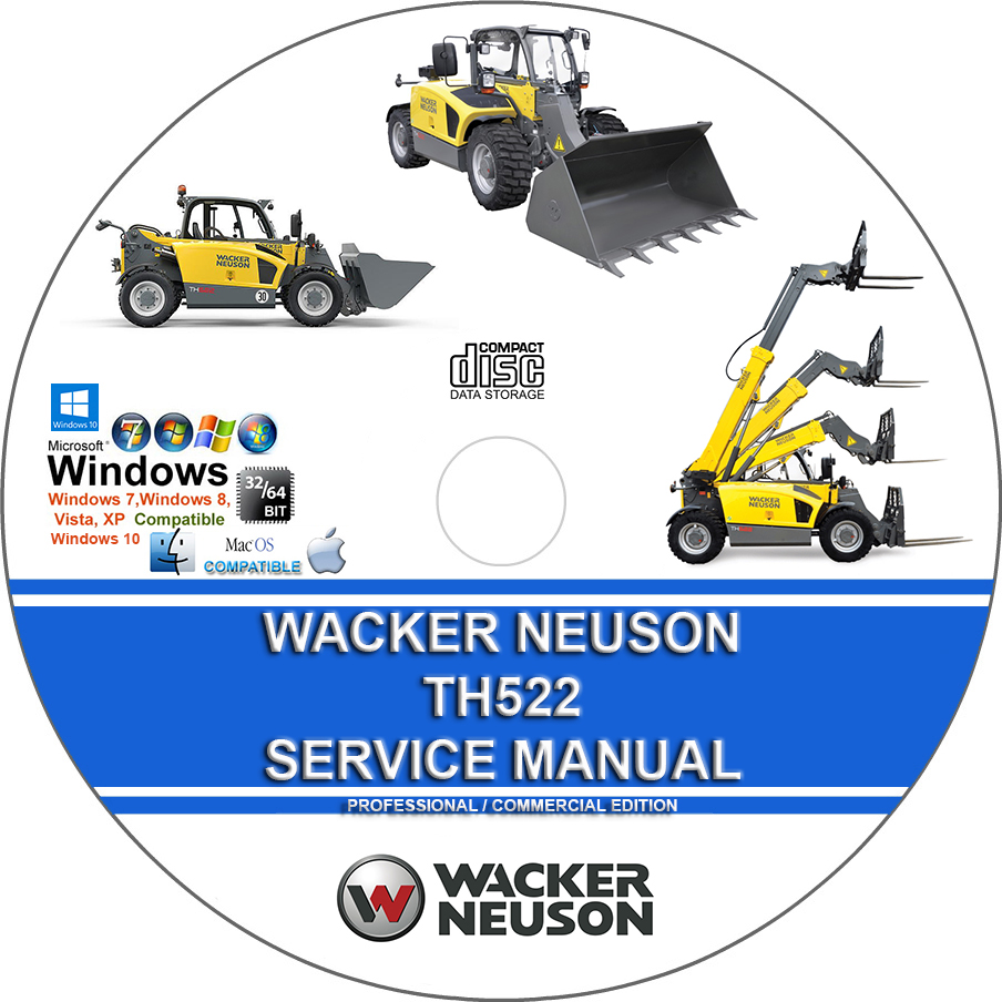
Wacker Neuson TH522 Telehandler Factory Service Repair Manual + Operators Manual + Parts Manual
$39.00 – $48.00Price range: $39.00 through $48.00
Wacker Neuson TH522 Telehandler Factory Service Repair Manual + Operators Manual + Parts Manual
You can download this or I can ship it to you.
Loaded with Hi Resolution illustrations, instructions, photos, and diagrams, complete to service and repair your Wacker Neuson.
2028 Pages
Wacker Neuson TH522 Telehandler Factory Service Repair Manual + Operators Manual + Parts Manual
Loaded with illustrations, instructions, photos, and diagrams, complete to service and repair your Wacker Neuson.
2028 Pages
MANUAL COVERS:
SERVICE REPAIR MANUAL:
Content:
E Introduction
E.1 About this Service Manual
E.2 Tightening torques
E.3 Safety instructions
B Operation
B.1 Overview of control elements
B.2 Indicator lights and warning lights (overview)
B.3 Steering system
B.4 Accelerator actuation
B.5 Brakes
B.6 Travel operation
B.7 Differential lock (option)
B.8 Lights/signaling system
B.9 Wiper/washer system
B.10 Heating, ventilation and air conditioning system
B.11 Operating hydraulics
B.12 Attachments
B.13 Work operation
B.14 Emergency lowering
B.15 Options
1 Maintenance:
1.1 Information on maintenance
1.2 Maintenance overview
1.3 Fluids and lubricants
1.4 Maintenance accesses
1.5 Cleaning and maintenance
1.6 Lubrication work
1.7 Fuel system
1.8 Engine lubrication system
1.9 Cooling system
1.10 Air filter
1.11 V-belt/toothed belt
1.12 Hydraulic system
1.13 Electrical system
1.14 Heating, ventilation and air conditioning system (option)
1.15 Washer system
1.16 Axles/traveling drive
1.17 Braking system
1.18 Tires
1.19 Maintenance and servicing work on attachments
1.20 Maintenance of options
1.21 Exhaust gas treatment
2 Engine:
2.1 Complete component (engine 36.7 kW)
2.2 Alternator (36.7 kW)
2.3 Motor starter M001 (36.7 kW)
2.4 Complete component (engine 44.3 kW)
2.5 Alternator (44.3 kW)
2.6 Motor starter M001 (44.3 kW)
2.7 Diesel particulate filter (engine 44.3 kW)
2.8 Fuel tank
2.9 Tank sensor B001
3 Cooling:
3.1 Coolant reservoir
4 Traveling drive:
4.1 Cardan shaft
4.2 Servomotor M17/M18
4.3 Type label – transfer gearbox
4.4 Tightening torques and screw locking
4.5 Drain, filler and check plugs
5 Axles:
5.1 Front axle
5.2 Rear axle
5.3 Type plate – front/rear axle
5.4 Tightening torques and screw locking
5.5 Drain, filler and check plugs
6 Brakes:
6.1 Replacing brake linings
7 Steering system:
7.1 Steering orbitrol S8
7.2 Steering mode valve V64
8 Hydraulic system:
8.1 Hydraulic oil tank Z41
8.2 Variable displacement pump P34/P35
8.3 Quick hitch
8.4 Telescopic boom
8.5 Lift cylinder A57
8.6 Push-out cylinder A59
8.7 Tilt cylinder A58
8.8 Compensation cylinder A60
8.9 Designation of hydraulic components
8.10 Hydraulics diagram – variant 1
8.11 Hydraulics diagram – variant 2
8.12 Hydraulic diagram – variant 3
8.13 Hydraulics diagram – variant 4
8.14 Hydraulics diagram – variant 5
8.15 Hydraulics diagram – 4-way control valve
8.16 Hydraulics diagram – 5-way control valve
8.17 Hydraulics diagram – 6-way control valve
8.18 Hydraulics diagram – 7-way control valve
8.19 Hydraulics diagram – 8-way control valve
8.20 Hydraulics diagram – compensating and lift cylinder
8.21 Hydraulics diagram – push-out cylinder
8.22 Hydraulics diagram – tilt cylinder
8.23 Hydraulics diagram – steering system
8.24 Hydraulic circuit diagram – brakes
8.25 Hydraulic circuit diagram – differential lock
8.26 Hydraulics diagram – 3rd control circuit parallel / 4th control circuit parallel with switchover valve
8.27 Hydraulics diagram – 3rd control circuit serial / 4th control circuit parallel
8.28 Hydraulics diagram – 3rd and 4th control circuit parallel, rear hydraulic connections serial
8.29 Hydraulics diagram – 3rd / 4th control circuit and rear hydraulics parallel, rear hydraulic connections
serial
8.30 Hydraulics diagram – 3rd / 4th control circuit and rear hydraulics parallel, rear hydraulic connections
serial, High Flow a
9 Electrical system:
9.1 Fuse assignment
9.2 Relays
9.3 Electrical components
9.4 Safe load indicator P006
9.5 Limit switches S116/S142
9.6 Malfunctions of the machine electronics (36.3 kW engine)
9.7 Malfunctions of the machine electronics (44.7 kW engine)
9.8 Error code table
9.9 Electrical diagram – electronics, power supply
9.10 Electrical diagram – Perkins 404D-22 engine
9.11 Electrical diagram – Perkins 404D-22 engine
9.12 Electrical diagram – Perkins 404F-22 engine
9.13 Electrical diagram – Perkins 404F-22 engine
9.14 Electrical diagram – Ciam instrument
9.15 Electrical diagram – Bauser instrument
9.16 Electrical diagram – drive function
9.17 Electrical diagram – extension and retraction; VLS; Load control
9.18 Electrical diagram – indicator system; Horn
9.19 Electrical diagram – StVZO (German traffic regulations) lights
9.20 Electrical diagram – StVZO (German traffic regulations) lights
9.21 Electrical diagram – working lights; Rotating beacon
9.22 Electrical diagram – air conditioning; Seat
9.23 Electrical diagram – wiper
9.24 Electrical diagram – 12V electrical connection; Hydraulic control circuits
9.25 Electrical diagram – Hydraulics 1
9.26 Electrical diagram – Hydraulics 2
9.27 Electrical diagram – Radio; Cigarette lighter socket; Interior light
9.28 Electrical diagram – rear force sensorr
9.29 Electrical diagram – steering mode switchover
9.30 Designation of electrical components
9.31 Connector pin assignment
9.32 Pin assignment (only 33.7 kW engine)
9.33 Pin assignment (only 44.3 kW engine)
10 Trim:
10.1 Engine cover
10.2 Underride protection
10.3 Rear covers
10.4 Cabin covers
11 Cabin:
11.1 Seat
11.2 Cabin
11.3 Air conditioning cooler
11.4 Air conditioning system compressor Y031
12 Automatic coupling:
12.1 Ball coupling
12.2 Automatic/rotating trailer coupling
12.3 Self-securing coupling
13 Switch:
13.1 Overview of switch assignment
Index
Wacker Neuson TH522 Load Charts (272 Pages)
Wacker Neuson TH522 Spare Parts List (861 Pages)
Wacker Neuson TH522 Load Charts
Wacker Neuson TH522 Technical Data (315 Pages)
Wacker Neuson TH522 Specs
This manual is the same as the manual used by workshops. Service Manual contains detailed instructions and step by step diagrams for all workshop procedures.
Language: English
Format: PDF – Indexed and Searchable
COMPATIBLE WITH ALL WINDOWS & MAC COMPUTERS
(WINDOWS 11, WINDOWS 10, WINDOWS 8 ETC.)
Windows/Mac/Tablet/Phone Friendly
- Engine: The TH522 is powered by a 60-horsepower Tier 4-Final Perkins turbo diesel engine.
- Transmission: A hydrostatic all-wheel-drive system delivers smooth power and a top travel speed of around 19 mph (30 km/h).
- Lifting capacity: It has a maximum lift capacity of approximately 5,500 pounds (2.5 tons) and a maximum lift height of 16 feet 7 inches (5.06 meters).
- Vertical Loading System (VLS): This feature, unique to Wacker Neuson, automates boom movements based on the operator’s input to enhance stability and reduce the risk of tipping. It offers two modes:
- Bucket mode: Retracts the boom as the operator lowers the bucket to keep the load close to the front axle.
- Fork mode: Extends and retracts the boom automatically to move a load vertically, like a forklift.
- Universal attachment plate: A hydraulically operated universal skid-steer style attachment plate allows the TH522 to use a wide range of attachments.
- Steering: Operators can choose between three steering modes for maximum flexibility in tight spaces: all-wheel, front-wheel, and crab steering.
- Hydraulic problems: Hydraulic leaks and loss of power are common, so regular inspection of fluid levels, seals, and gaskets is important.
- Electrical system: Faulty sensors, loose connections, or battery issues can cause performance problems. Wacker Neuson offers a diagnostic and analysis tool called WANDA for troubleshooting these issues.
- Engine performance: Some Perkins engines can experience power issues, even without fault codes. This can sometimes be related to exhaust temperature, filters, or fuel delivery.
- Load management: The onboard digital display monitors the machine’s load and provides visual and audible alerts to prevent tipping, but it is important to follow proper lifting techniques.
- Pallet forks
- General-purpose buckets
- Augers
- Concrete mixing buckets
- Snowplows or mulchers with optional high-flow hydraulics
| Medium | USB Flash Drive, DVD, Download |
|---|
Related products
CAT Caterpillar
Heavy Machinery
John Deere 3032E 3036E 3038E Compact Utility Tractor Factory Workshop Service Repair Manual TM100619
Heavy Machinery
Heavy Machinery
Heavy Machinery
John Deere X465 X475 X485 X575 X585 Garden Tractors TM2023 Factory Service Repair Manual
