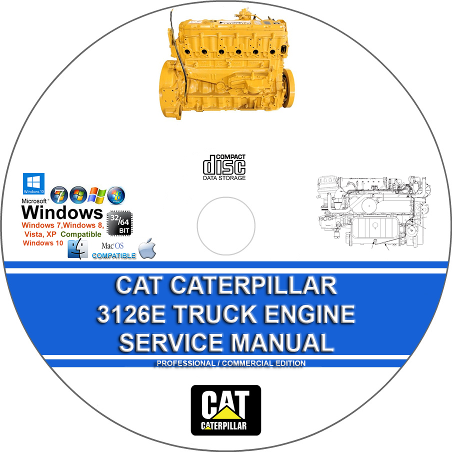
Cat Caterpillar 3126E Truck Engine Workshop Factory Service Repair Manual
$39.00 – $48.00Price range: $39.00 through $48.00
Cat Caterpillar 3126E Truck Engine Workshop Factory Service Repair Manual
You can download this or I can ship it to you.
Loaded with Hi Resolution illustrations, instructions, photos, and diagrams, complete to service and repair your CAT CATERPILLAR.
Cat Caterpillar 3126E Truck Engine Workshop Factory Service Repair Manual
Loaded with illustrations, instructions, photos, and diagrams, complete to service and repair your engine.
MODEL COVERSTHE FOLLOWING SERIAL NUMBERS:
– BKD1-Up
– G3E1-Up
– DPF1-Up
– 1AJ1-Up
– 8YL1-Up
– CRP1-Up
– CKM1-Up
– 7AS1-Up
– 8SZ1-Up
– 9SZ1-Up
MANUAL COVERS:
Schematic (3126E Truck Engine Electrical System)
Systems Operation (3126E Truck Engines):
Air Inlet and Exhaust System
Basic Engine
Cooling System
Electrical System
Electronic Control System Components
Engine Design
Exhaust Brake
Fuel System
General Information
Glossary of Electronic Control Terms
Lubrication System
Rear Power Take-Off (RPTO)
Testing and Adjusting (3126E Truck Engines):
Aftercooler – Test
Air in Fuel – Test
Air Inlet and Exhaust System – Inspect
Alternator – Test
Battery – Test
Belt Tension Chart
Bore Run out (Radial Eccentricity) of the Flywheel Housing
Charging System – Test
Compression – Test
Connecting Rod Bearings – Inspect
Cooling System – Check – Overheating
Cooling System – Inspect
Cooling System – Test
Cylinder Block – Inspect
Electric Starting System – Test
Electronic Unit Injector – Test
Engine Crankcase Pressure (Blowby) – Test
Engine Oil Pressure – Test
Engine Oil Pressure Sensor – Test
Engine Oil Pump – Inspect
Engine Speed – Check
Engine Valve Lash – Inspect Adjust
Excessive Bearing Wear – Inspect
Excessive Engine Oil Consumption – Inspect
Exhaust Temperature – Test
Finding Top Center Position for No. 1 Piston
Flywheel – Inspect
Fuel Quality – Test
Fuel System – Inspect
Fuel System – Prime
Fuel System Pressure – Test
Gear Group (Front) – Time
Increased Engine Oil Temperature – Inspect
Inlet Manifold Pressure – Test
Main Bearings – Inspect
Pinion Clearance – Adjust
Piston Ring Groove – Inspect
Turbocharger – Inspect
Vibration Damper – Check
Water Pump – Test
Water Temperature Regulator – Test
Specifications (3126E Truck Engine):
Air Compressor – Bendix Tu-Flo Air Compressors
Air Compressor – Midland Air Compressors
Air Inlet Elbow
Air Inlet Heater
Alternator and Regulator
Atmospheric Pressure Sensor – If Equipped
Belt Tension Chart
Belt Tensioner
Belt Tightener
Boost Pressure Sensor
Camshaft
Connecting Rod
Connecting Rod Bearing Journal
Coolant Temperature Sensor
Crankcase Breather
Crankshaft
Crankshaft Pulley
Crankshaft Seals
Cylinder Block
Cylinder Block Cover Group
Cylinder Head
Cylinder Head Valves
Electric Starting Motor
Electronic Control Wiring Group
Engine Design
Engine Oil Filter Base
Engine Oil Lines
Engine Oil Pan
Engine Oil Pressure Sensor – If Equipped
Engine Oil Pump
Engine to Transmission Adapter
Exhaust Brake
Exhaust Elbow
Exhaust Manifold
Fan Drive Mounting Group
Flywheel
Flywheel Housing
Front Housing and Covers
Fuel Filter Base
Gear Group (Front)
Inlet Air Temperature Sensor
Main Bearing Journal
Piston and Rings
Piston Cooling Jet
Rear Seal Carrier – If Equipped
Refrigerant Compressor
Speed Timing Sensor
Tech doc print page
Turbocharger
Unit Injector
Unit Injector Hydraulic Pump
Valve Mechanism Cover
Valve Rocker Arms, Lifters, and Bridges
Vibration Damper
Water Pump
Water Temperature Regulator
Disassembly and Assembly (3126E On-highway Engine):
Air Compressor – Remove and Install
Air Compressor Drive Gear – Remove and Install
Air Inlet Cover – Remove and Install
Air Inlet Heater – Remove and Install
Air Inlet Heater Solenoid – Remove and Install
Alternator – Remove and Install
Atmospheric Pressure Sensor – Remove and Install
Bearing Clearance – Check
Belt Tensioner – Remove and Install
Belt Tightener – Assemble
Belt Tightener – Disassemble
Belt Tightener – Install
Belt Tightener – Remove
Boost Pressure Sensor – Remove and Install
Camshaft – Install
Camshaft – Remove
Camshaft Bearings – Install
Camshaft Bearings – Remove
Camshaft Gear – Remove and Install
Camshaft Idler Gear – Remove and Install
Connecting Rod Bearings – Install
Coolant Temperature Sensor – Remove and Install
Crankshaft – Install
Crankshaft – Remove
Crankshaft Front Seal – Remove
Crankshaft Gear – Remove and Install
Crankshaft Main Bearings – Install
Crankshaft Main Bearings – Remove
Crankshaft Rear Seal – Install
Crankshaft Rear Seal – Remove
Crankshaft Rear Seal Carrier – Remove and Install
Crankshaft Wear Sleeve (Rear) – Install
Crankshaft Wear Sleeve (Rear) – Remove – If Equipped
Cylinder Head – Install
Cylinder Head – Remove
Electric Starting Motor – Remove and Install
Engine Control Module – Remove and Install
Engine Oil Filter Base – Assemble
Engine Oil Filter Base – Disassemble
Engine Oil Filter Base – Install
Engine Oil Filter Base – Remove
Engine Oil Pan – Remove and Install
Engine Oil Pressure Sensor – Remove and Install
Engine Oil Pump – Assemble
Engine Oil Pump – Disassemble
Engine Oil Pump – Install
Engine Oil Pump – Remove
Exhaust Manifold – Remove and Install
Fan Drive – Install
Fan Drive – Remove
Fan Drive Mounting Group – Remove and Install
Flywheel – Remove and Install
Flywheel Housing – Remove and Install
Front Cover – Install
Front Cover – Remove
Fuel Filter Base – Install
Fuel Filter Base – Remove
Fuel Pressure Regulator – Remove and Install
Fuel Transfer Pump – Install
Fuel Transfer Pump – Remove
Housing (Front) – Install
Housing (Front) – Remove
Idler Pulley – Assemble
Idler Pulley – Disassemble
Idler Pulley – Install
Idler Pulley – Remove
Inlet Air Temperature Sensor – Remove and Install
Inlet and Exhaust Valve Guides – Remove and Install
Inlet and Exhaust Valve Seat Inserts – Remove and Install
Inlet and Exhaust Valves – Remove and Install
Installation Procedure
Lifter Group – Remove and Install
Piston Cooling Jets – Remove and Install
Pistons and Connecting Rods – Assemble
Pistons and Connecting Rods – Disassemble
Pistons and Connecting Rods – Install
Pistons and Connecting Rods – Remove
Rear Power Take-Off (RPTO) – Install
Rear Power Take-Off (RPTO) – Remove
Rocker Shaft – Assemble
Rocker Shaft – Disassemble
Rocker Shaft and Pushrod – Install
Rocker Shaft and Pushrod – Remove
Speed Timing Sensor – Remove and Install
Turbocharger – Install
Turbocharger – Remove
Unit Injector – Install
Unit Injector – Remove
Unit Injector Hydraulic Pump – Install
Unit Injector Hydraulic Pump – Remove
Unit Injector Sleeve – Install
Unit Injector Sleeve – Remove
Valve Mechanism Cover – Remove and Install
Valve Mechanism Cover Base – Remove and Install
Vibration Damper and Pulley – Remove and Install
Water Pump – Assemble
Water Pump – Disassemble
Water Pump – Install
Water Pump – Remove
Water Temperature Regulator – Remove and Install
Troubleshooting (3126E On-highway Engine):
0001-11 Cylinder #1 Injector current fault (72)
0002-11 Cylinder #2 Injector current fault (72)
0003-11 Cylinder #3 Injector current fault (73)
0004-11 Cylinder #4 Injector current fault (73)
0005-11 Cylinder #5 Injector current fault (74)
0006-11 Cylinder #6 Injector current fault (74)
0022-13 Engine Speed Signal Calibration Not Performed (42)
0030-08 PTO Throttle signal invalid (29)
0030-13 PTO Throttle out of calibration (29)
0041-03 8 Volt Supply voltage high (21)
0041-04 8 Volt Supply voltage low (21)
0042-11 Injection Actuation Pressure output fault
0043-02 Key Switch Fault (71)
0064-02 Secondary Engine Speed loss of signal (34)
0064-11 Secondary Engine Speed no pattern (34)
0070-05 Inlet Air Heater current low
0070-06 Inlet Air Heater current high
0071-00 Idle Shutdown Override (01)
0071-01 Idle Shutdown (47)
0071-14 PTO Shutdown (47)
0084-00 Vehicle Overspeed Warning (41)
0084-01 Vehicle Speed loss of signal (31)
0084-02 Vehicle Speed signal invalid (36)
0084-08 Vehicle Speed signal out of range (36)
0084-10 Vehicle Speed signal rate of change (36)
0091-08 Throttle Position Invalid (32)
0091-13 Throttle Position out of calibration (28)
0096-03 Fuel Level voltage high
0096-04 Fuel Level voltage low
0100-03 Oil Pressure voltage high (24)
0100-04 Oil Pressure voltage low (24)
0100-11 Very Low Oil Pressure (46)
0102-03 Boost Pressure voltage high (25)
0102-04 Boost Pressure voltage low (25)
0102-07 Boost Pressure not responding
0105-00 High Intake Manifold Air Temperature Warning (64)
0105-03 Intake Manifold Air Temperature voltage high (38)
0105-04 Intake Manifold Air Temperature voltage low (38)
0105-11 Very High Intake Manifold Air Temperature (64)
0108-03 Barometric Pressure voltage high (26)
0108-04 Barometric Pressure voltage low (26)
0110-00 High Coolant Temperature Warning (61)
0110-03 Coolant Temperature voltage high (27)
0110-04 Coolant Temperature voltage low (27)
0110-11 Very High Coolant Temperature (61)
0111-01 Low Coolant Level Warning (62)
0111-02 Coolant Level signal invalid (12)
0111-03 Coolant Level voltage high (12)
0111-04 Coolant Level voltage low (12)
0111-11 Very Low Coolant Level (62)
0128-03 Secondary Fuel Level voltage high
0128-04 Secondary Fuel Level voltage low
0164-00 Excessive Injection Actuation Pressure (17)
0164-02 Injection Actuation Pressure Signal Erratic (15)
0164-03 Injection Actuation Pressure voltage high (15)
0164-04 Injection Actuation Pressure voltage low (15)
0164-11 Injection Actuation Pressure system fault (39)
0168-02 ECM Battery Power Intermittent (51)
0186-04 PTO Engine Shutdown Switch voltage low
0186-14 PTO Engine Shutdown Switch Occurrence (47)
0190-00 Engine Overspeed Warning (35)
0190-02 Primary Engine Speed Loss of Signal (34)
0190-11 Primary Engine Speed no pattern (34)
0224-11 Theft Deterrent Active (00)
0224-14 Theft Deterrent Active with Engine Cranking (00)
0231-02 J1939 Data Incorrect (58)
0231-11 J1939 Data Link Fault (58)
0231-12 J1939 Device Not Responding
0232-03 5 Volt Supply voltage high (21)
0232-04 5 Volt Supply voltage low (21)
0246-11 Brake Pedal Switch #1 Fault
0247-11 Brake Pedal Switch #2 Fault
0252-11 Engine Software Incorrect (59)
0253-02 Check Customer or System Parameters (56)
0253-14 Truck Manufacturer Parameter Not Programed
5 Volt Engine Pressure Sensor Supply Circuit – Test
Accelerator Pedal (Throttle) Position Sensor Circuit – Test
Air Inlet Heater Circuit – Test
ATA (SAE J1587 J1708) Data Link Circuit – Test
Can Not Reach Top Engine RPM
Can Not Reach Vehicle Speed Limit
Change Oil Lamp Circuit – Test
Check Engine Lamp Circuit – Test
Check Engine Lamp or Warning Lamp Is Malfunctioning
Clutch Pedal Position Switch Circuit – Test
Coolant Level Sensor Circuit – Test
Cooling Fan Circuit and A/C High Pressure Switch Circuit – Test
Cruise Control Parameters
Cruise Control, Idle, or PTO Can Not Be Set
Customer Passwords
Customer Specified Parameters
Customer Specified Parameters Table
Customer Specified Parameters Worksheet
Data Link Parameters
Dedicated PTO Parameters
Diagnostic Codes
Diagnostic Enable Switch Circuit – Test
Driver Questionnaire
Driver Questionnaire Response
ECM Memory – Test
ECM Snapshot
ECM Will Not Accept Factory Passwords
Electrical Connectors – Inspect
Electronic Service Tool Will Not Communicate with ECM
Electronic Service Tools
Elevated Idle
Engine Cranks but Will Not Start
Engine Has Early Wear
Engine Misfires, Runs Rough or Is Unstable
Engine Monitoring Parameters
Engine Pressure Sensor Open or Short Circuit – Test
Engine Running Output Circuit – Test
Engine Speed Timing Sensor Circuit – Test
Engine Temperature Sensor Open or Short Circuit – Test
Engine Vibration
Engine Will Not Crank
Excessive Black Smoke
Excessive Fuel Consumption
Excessive White Smoke
Exhaust Brake Circuit – Test
Factory Passwords
Factory Passwords Worksheet
Fast Idle Enable Circuit – Test
Fast Idle Lamp Circuit – Test
Fuel Level Sensor Circuit – Test
Idle Parameters
Idle Shutdown Timer – Test
Ignition Key switch Circuit and Battery Supply Circuit – Test
Ignore Brake Clutch Switch Circuit – Test
Injection Actuation Pressure – Test
Injection Actuation Pressure Control Valve Circuit – Test
Injection Actuation Pressure Sensor – Test
Injector Solenoid Circuit – Test
Input Selections
Intermediate Gears Engine RPM Limit
Intermittent Cruise Control, Idle, or PTO Kickout
Intermittent Engine Shutdown
Intermittent Low Power or Power Cutout
Low Power Poor or No Response to Throttle
Maintenance Parameters
Neutral Switch Circuit – Test
No Diagnostic Code Detected (55)
Output Selections
Passwords
Poor Acceleration or Response
Powertrain Data Link Circuit – Test
Programming Parameters
PTO Engine RPM Set Speed (Input A and Input B) Circuit – Test
PTO Engine Shutdown Switch Circuit – Test
PTO Shutdown Timer – Test
PTO Switch Circuit – Test
PTO Switch ON Lamp Circuit – Test
Remote PTO Accelerator Position Sensor Circuit – Test
Replacing the ECM
Selected Engine Rating
Sensors and Electrical Connectors
Service Brake Pedal Position (Switch 1) Circuit – Test
Service Brake Pedal Position (Switch 2) Circuit – Test
Service Information Report
Smart Idle Parameters
Starting Aid Output Circuit – Test
System Configuration Parameters
System Overview
Tachometer Circuit – Test
Test ECM Mode
Time Stamped Information
Timer Parameters
Timing Sensor – Calibrate
Trip Parameters
Truck Manufacture Parameters
Two Speed Axle Switch Circuit – Test
Vehicle Speed and Speedometer Circuit – Test
Vehicle Speed Circuit – Calibrate
Vehicle Speed Parameters
Wait To Start Lamp Circuit – Test
Warning Lamp Circuit – Test
Bonus Material:
Battery Cross Ref
Battery Specs
Cooling System (3126B & 3126E)
DSTC
Fuel System (3126B & 3126E)
Intake, Exhaust & Turbocharger (3126B & 3126E)
Lubrication (3126B & 3126E)
Mechanical (3126B & 3126E)
One Safe Source
RENR1368 – Schematic (3126B and 3126E On-highway Engines)
SENR9675-00-01-ALL
Shop Supplies & Tools
Troubleshooting (3126B & 3126E)
This manual is the same as the manual used by workshops. Service Manual contains detailed instructions and step by step diagrams for all workshop procedures.
Language: English
Format: PDF
COMPATIBLE WITH ALL WINDOWS & MAC COMPUTERS
(WINDOWS 10, WINDOWS 8, WINDOWS 11, ETC.)
Windows/Mac/Tablet/Phone Friendly
| Medium | USB Flash Drive, DVD, Download |
|---|
Related products
Heavy Machinery
John Deere X495 X595 4WD Diesel Garden Tractors TM2024 Factory Service Repair Manual
Heavy Machinery
