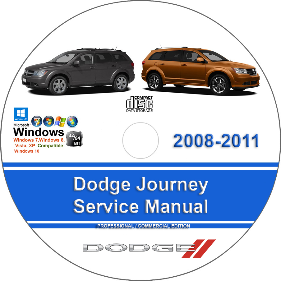
Dodge Journey 2008 2009 2010 2011 Factory Service Repair Manual + Wiring
$40.00 – $49.00Price range: $40.00 through $49.00
Dodge Journey 2008 2009 2010 2011 Factory Service Repair Manual + Wiring
You can download this or I can ship it to you.
Loaded with Hi Resolution illustrations, instructions, photos, and diagrams, complete to service and repair your Dodge.
Pages: 12000+
Dodge Journey 2008 2009 2010 2011 Factory Service Repair Manual + Wiring
Models Covered :
2009 Version Compatible with:
Dodge Journey 2008
Dodge Journey 2009
Dodge Journey 2010
Dodge Journey 2011
Like the greater part of Dodge’s 2011 lineup, the 2011 Dodge Journey gets additionally brave outside styling combined with an all-as good as ever inside. Accessible on five trim levels beginning with the Express and going through the Mainstreet, Crew, R/T to in the long run top out at the LUX, utility for the 2011 Journey is clear all through the lineup. An in-floor stockpiling canister, payload secure circles and 12-volt helper electrical plugs are discovered standard on each model. Normally a five-traveler hybrid on everything except the Journey LUX, seating for up to 7 tenants is an alternative on the Express, Mainstreet and Crew levels. Other than the reshaped styling for 2011, the Dodge Journey gets the Pentastar V-6 force plant useful for 283 strength through either front-wheel or all-wheel drive. For the passage level Express trim model of the 2011 Dodge Journey, the 2.4 liter inline four-chamber motor returns as an abundantly controlled however more eco-friendly decision. The littler four-chamber power plant is useful for an additional mile for every gallon normal over a front-wheel drive Pentastar V-6 Journey.Dodge would have liked to lift the remaining of the Journey in the market with 2011’s renewed model and with accessible all-wheel drive, an incredible new V6 motor and sportier suspension feel all remembered for the current year’s update, they’ve made it significantly increasingly serious in a market overwhelmed by the Honda Pilot, Ford Flex, Chevrolet Traverse, Mazda CX-9 and Toyota Highlander.
Manual Covers :
Accessories and Equipment:
Audio (Amplifier) – Electrical Diagnostics
Audio (Radio) – Electrical Diagnostics
Audio and Video – Service Information
Audio Video – Non-DTC Diagnostics
Body
Cabin Compartment Node (CCN) – Electrical Diagnostics
Chime Buzzer – Service Information
Communication – Non-DTC Diagnostics
Driver Door Module (DDM) (DMFLR) – Electrical Diagnostics
Electronic Control Modules – Service Information
Frame and Bumpers
Hands Free Module (HFM) – Electrical Diagnostics
Heated Glass – Service Information
Heated Mirrors – Service Information
Heated Seats – Service Information
Horn System – Service Information
Instrument Cluster – Non-DTC Diagnostics
Instrument Cluster – Service Information
Intrusion Transceiver Module (ITM) – Electrical Diagnostics
Lamps Lighting – Exterior – Service Information
Lamps Lighting – Interior – Service Information
Message Center – Service Information
Navigation Telecommunication – Service Information
Overhead Console – Service Information
Passenger Door Module (PDM) (DMFLR) – Electrical Diagnostics
Power Distribution
Power Doors – Non-DTC Diagnostics
Power Locks – Service Information
Power Mirrors – Service Information
Power Seats – Service Information
Power Top, Sunroof – Service Information
Power Windows – Non-DTC-Based Diagnostics
Power Windows – Service Information
Radio Display Module (DISP) – Electrical Diagnostics
Speed Control – Non-DTC-Based Diagnostics
Speed Control – Service Information
Totally Integrated Power Module (TIPM) – Electrical Diagnostics – Standard Procedure
Totally Integrated Power Module (TIPM) – Electrical Diagnostics – Diagnostic Code Index
Totally Integrated Power Module (TIPM) – Electrical Diagnostics – B10E9 To B1647
Totally Integrated Power Module (TIPM) – Electrical Diagnostics – B1648 To B198B
Totally Integrated Power Module (TIPM) – Electrical Diagnostics – B2101 To P0462
Totally Integrated Power Module (TIPM) – Electrical Diagnostics – P0462 To P128D
Totally Integrated Power Module (TIPM) – Electrical Diagnostics – P128E To U0186
Totally Integrated Power Module (TIPM) – Electrical Diagnostics – U0197 To U1148
Universal Transmitter
Vehicle Theft Security – Service Information
Video Entertainment System (VES3) – Electrical Diagnostics
Video Satellite (SDARV) – Electrical Diagnostics
Wipers Washers – Service Information
Wireless Ignition Module (WIN) – Electrical Diagnostics
Wiring Harness – Service Information
Ateq Tpms Reset Procedure:
Ateq Tpms Reset Procedure
Automatic Stop/ Start Disable:
Automatic Stop/ Start Disable
Automatic Transmission:
41TE – Service Information
62TE – Service Information
Getrag MPS6 – Service Information
Powertrain Control Module – Electrical Diagnostics – 41TE – GPEC
Powertrain Control Module – Electrical Diagnostics – 62TE
Transmission Control Module – Electrical Diagnostics
Bartec Tpms Reset Procedure:
Bartec Tpms Reset Procedure
Brakes:
ABS – Electrical Diagnostics
ABS – Service Information
Base – Service Information
Cabin Air Filter:
Cabin Air Filter
Canadian Model Reference:
Canadian Model Reference
Electrical Component Locator:
Electrical Component Locator
Clutch:
Clutch
Driveline and Axles:
All Wheel Drive (AWD) Module – Electrical Diagnostics
Differential and Driveline
DTC Index:
DTC Index
EGR Function Testing:
EGR Function Testing
Electrical:
Battery System
Charging – Service Information
Fuses & Circuit Breakers
Emission:
Applications
Control Abbreviations
Engine Performance:
Drive ability – Gas – Non-DTC Diagnostics
Emissions Control
Firing Order & Cylinder Identification
Mode 6
O2 Sensor Location & Identification
Powertrain Control Module – Electrical Diagnostics – GPEC – Diagnostic Code Index
Powertrain Control Module – Electrical Diagnostics – GPEC – P000A To P0122
Powertrain Control Module – Electrical Diagnostics – GPEC – U0402 To U1418
Powertrain Control Module – Electrical Diagnostics – GPEC – Standard Procedure
Powertrain Control Module – Electrical Diagnostics – GPEC – P0123 To P0262
Powertrain Control Module – Electrical Diagnostics – GPEC – P0264 To P0440
Powertrain Control Module – Electrical Diagnostics – GPEC – P0441 To P0533
Powertrain Control Module – Electrical Diagnostics – GPEC – P0562 To P0625
Powertrain Control Module – Electrical Diagnostics – GPEC – P0626 To P1513
Powertrain Control Module – Electrical Diagnostics – GPEC – P1572 To P2101
Powertrain Control Module – Electrical Diagnostics – GPEC – P2106 To P2184
Powertrain Control Module – Electrical Diagnostics – GPEC – P2185 To U0168
Powertrain Control Module – Electrical Diagnostics – NGC – Diagnostic Code Index
Powertrain Control Module – Electrical Diagnostics – NGC – P0016 To P0129
Powertrain Control Module – Electrical Diagnostics – NGC – Standard Procedure
Powertrain Control Module – Electrical Diagnostics – NGC – P0131 To P0204
Powertrain Control Module – Electrical Diagnostics – NGC – P0205 To P0430
Powertrain Control Module – Electrical Diagnostics – NGC – P0440 To P0571
Powertrain Control Module – Electrical Diagnostics – NGC – P0572 To P0642
Powertrain Control Module – Electrical Diagnostics – NGC – P0643 To P1897
Powertrain Control Module – Electrical Diagnostics – NGC – P2008 To P2128
Powertrain Control Module – Electrical Diagnostics – NGC – P2135 To U0121
Powertrain Control Module – Electrical Diagnostics – NGC – U0141 To U1418
Engine:
2.4L Gas – Service Information
2.7L DOHC – Service Information
3.5L – Service Information
Cooling System
Exhaust System
Fuel System
Ignition Control – Service Information
Starting – Non-DTC Diagnostics
Starting – Service Information
General Information:
Anti-Lock Brake Safety Precautions
Clutch Trouble Shooting
Commonly Used Abbreviations
Diagnostic Connector (DLC) Locations
Drive Axle Noise Diagnosis
Electrostatic Discharge (ESD) Warning – Basic Information
Engine Displacement Conversion Table
Engine Overhaul Procedures
Engine Performance Diagnostic Routine Outline
Engine Performance Safety Precautions
English-Metric Conversion Chart
Gear Tooth Contact Patterns
General Cooling System Service
Manual Transmission Trouble Shooting
Mopar Accessories
Parasitic Load Explanation & Test Procedures
Special Tools – DTC-Based Diagnostics
Special Tools – Non-DTC-Based Diagnostics
State Emission Standards – Gasoline
State Emission Standards
Symptom Check List Worksheets
Trouble Shooting – Basic Procedures
TROUBLE SHOOTING
Using Wiring Diagrams
Vehicle Data
Vehicle Quick Reference
Waveforms – Injector Pattern Tutorial
Wheel Alignment Theory & Operation
HVAC:
Heating & Air Conditioning – Service Information
Heating & Air Conditioning (ATC) – Electrical Diagnostics
Heating & Air Conditioning (MTC Three Zone) – Electrical Diagnostics
Heating & Air Conditioning (MTC) – Electrical Diagnostic
Manual Transmission:
BG6 – Service Information
T355 – Service Information
OBD-II Readiness Monitors:
OBD-II Readiness Monitors
Reminder Indicator Reset Procedures:
Reminder Indicator Reset Procedures
Restraints:
Electrical Diagnostics
Service Information
Specifications Index:
Specifications Index
Steering:
Steering
Suspension:
Front Suspension
Rear Suspension
Tires Wheels – Service Information
System Wiring Diagrams:
Wiring Diagrams
Tire Pressure Monitor System:
Tire Pressure Monitor System
Traction Control:
4WD and AWD
Transfer Case – Power Unit:
Transfer Case – Power Unit
Uniform Inspection and Communication Standards:
Brake Systems
Drive Train & Transmission Systems
Electrical Systems
Engine Performance And Maintenance
Exhaust Systems
Heating, Ventilation And Air Conditioning Systems
Routine Inspection Reference Guide
Steering & Suspension Systems
This manual is the same as the manual used by workshops. Service Manual contains detailed instructions and step by step diagrams for all workshop procedures.
Language: English
Format: PDF
COMPATIBLE WITH ALL WINDOWS & MAC COMPUTERS
(WINDOWS 11, WINDOWS 10, WINDOWS 8, ETC.)
Windows/Mac/Tablet/Phone Friendly
| Medium | USB Flash Drive, DVD, Download |
|---|

