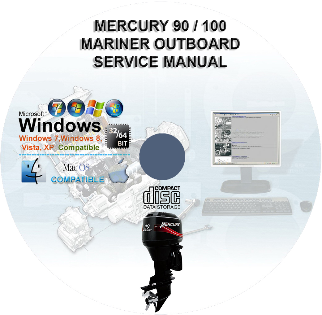
Mercury 90 US 100 EU Four Stroke EFI Factory Service Repair Manual
$34.00 – $40.00Price range: $34.00 through $40.00
Mercury 90 US 100 EU Four Stroke EFI Factory Service Repair Manual
You can download this or I can ship it to you.
Loaded with illustrations, instructions, photos, and diagrams, complete to service and repair your Mercury.
Covers 687 Pages
SKU: N/A
Categories: Mercury, Watercrafts/Boats
Mercury 90 US 100 EU Four Stroke EFI Factory Service Repair Manual
Models Covered :
Mercury 90 US
Mercury 100 EU
Manual Covers :
- Master Specifications :
- Table of Contents
- General Specifications
- Fuel System Specifications
- Ignition Specifications
- Charging and Starting Specifications
- Cylinder Block/Crankcase Specifications
- Cylinder Head Specifications
- Oil System Specifications
- Mid-Section Specifications
- Power Trim Specifications
- Gear Housing Specifications
- Hydraulic Steering Specifications
- 75 80 EU EFI Four Stroke Propeller Information Chart
- 90 100 EU EFI Four Stroke Propeller Information Chart
- 115 EFI Four Stroke Propeller Information Chart
- Maintenance :
- EPA Emissions
- Inspection and Maintenance Schedule
- Corrosion Control Anode
- Battery Inspection
- Alternator Drive Belt Inspection
- Flushing the Cooling System
- Top Cowl Removal and Installation
- Flywheel Cover Removal and Installation
- Cleaning Care for Top and Bottom Cowls
- Cleaning Care for the Powerhead
- Air Filter
- Fuel System
- Checking Power Trim Fluid
- Checking Engine Oil Level
- Changing Engine Oil
- Spark Plug Inspection and Replacement
- Fuse Replacement
- Propeller Replacement
- Lubrication Points
- Gearcase Lubrication
- Storage
- General Information :
- Serial Number Location
- Powerhead Front View
- Powerhead Starboard View
- Powerhead Port View
- Powerhead Aft View
- Conditions Affecting Performance
- Following Complete Engine Submersion
- Fuel and Oil
- Warning System
- Power Trim and Tilt
- Compression Check
- Cylinder Leakage Testing
- Painting Procedures
- Decal Removal
- Decal Application
- Outboard Motor Installation :
- Important Information
- Boat Horsepower Capacity
- Start in Gear Protection
- Selecting Accessories for your Outboard
- Fuel Tanks
- Filling the Fuel System
- Installation Specifications
- Lifting Outboard
- Steering Cable- Starboard Side Routed Cable
- Steering Link Rod Fasteners
- Determining Recommended Outboard Mounting
- Height
- Drilling Outboard Mounting Holes
- Fastening the Outboard to the Transom
- Electrical, Fuel Hose, and Control Cables
- Trim in Pin
- Ignition :
- Ignition Specifications
- Electrical Components
- Electrical Plate Components
- Cylinder Head and Camshaft Components
- Integrated Air Fuel Module Components
- Troubleshooting without a Computer Diagnostic System
- Troubleshooting with a Computer Diagnostic System
- Troubleshooting Guide
- Flywheel
- Electronic Control Module
- Wire Color Code Abbreviations
- Main Power Rely
- Ignition Pencil Coil
- Crankshaft Position Sensor
- Camshaft Position Sensor
- Throttle Position Sensor
- Cylinder Block Coolant Temperature Sensor
- Manifold Absolute Pressure Sensor
- Manifold Intake Air Temperature Sensor
- Oil Pressure Sensor
- Charging and Starting System :
- Charging and Starting Specifications
- Alternator/Starboard Cylinder Block Components
- Electrical Components
- Electrical Plate Components
- Starter Motor
- Battery
- Wire Harness Replacement
- Alternator System
- Starter System
- Timing, Synchronizing and Adjusting :
- Ignition Specifications
- Idle Timing Adjustment
- Maximum Timing Adjustment
- Throttle Cable Adjustment
- Theory of Operation :
- Air Induction System
- Fuel Injection System
- Air Induction and Fuel Injection System
- Troubleshooting and Diagnostics :
- Fuel System Specifications
- Troubleshooting with the Computer Diagnostic System
- Troubleshooting without a Computer Diagnostic System
- Guardian Protection System
- Fuel System Component Troubleshooting and Diagnostics
- Fuel System :
- Fuel System Specifications
- Fuel System Module Components
- Integrated Air Fuel Module
- Integrated Air Fuel Module Components
- Fuel System Module Mount Components
- Fuel System Module Mount Components
- Fuel System Module Hoses
- Throttle Position Sensor Removal and Installation
- Idle Air Control Removal and Installation
- Vent Canister Purge Valve Removal and Installation
- Vent Canister Switch Removal and Installation
- Fuel Rail
- Intake Manifold
- Fuel System Module
- Emissions :
- Exhaust Emission Standards
- Outboard Hydrocarbon Emissions Reduction
- Manufacturers Certification Label
- Service Replacement EPA Decal
- Powerhead :
- Cylinder Block/Crankcase Specifications
- Cylinder Block Components
- Crankshaft, Piston and Connecting Rod Components
- Lower Cowl Removal
- Powerhead Removal
- Removing Powerhead Components
- Powerhead Disassembly
- Cleaning, Inspection and Repair
- Powerhead Reassembly
- Installing Powerhead Components
- Powerhead Installation
- Lower Cowl Installation
- Engine Break-in Procedure
- Cylinder Head :
- Cylinder Head Specifications
- Cylinder Head and Camshaft Components
- Cylinder Head Disassembly
- Cleaning/Inspection/Repair
- Cylinder Head Reassembly
- Valve Clearance and Adjustments
- Lubrication :
- Oil System Specifications
- Oil Pump Components
- Engine Guardian System
- Oil Pump
- Mid-Section :
- Mid-Section Specifications
- Swivel Bracket and Steering Arm Components
- Transom Bracket Components
- Adapter Plate Components
- Oil Pump Components
- Driveshaft Housing Components
- Bottom Cowl Components
- Bottom Cowl Removal and Installation
- Lower Mount
- Adapter Plate and Driveshaft Housing Removal
- Transom/Swivel Bracket
- Adapter Plate and Driveshaft Housing Reassembly
- Shift Shaft Installation
- Power Trim :
- Power Trim Specifications
- Power Trim Components
- Power Trim General Information
- Wire Color Code Abbreviations
- Power Trim Flow Diagrams
- Troubleshooting
- Testing the Power Trim System with Test Gauge Kit
- Power Trim System Removal
- Power Trim Disassembly
- Shock Rod Disassembly
- Memory Piston Removal
- Power Trim Cleaning, Inspection and Repair
- Power Trim Assembly
- Power Trim System Installation
- Lower Unit :
- Gear Housing Specifications
- Gear Housing EZ Shift Components
- Gear Housing EZ Shift Components
- General Service Recommendations
- Draining and Inspecting Gear Housing Lubricant
- Gear Housing Removal
- Gear Housing Disassembly
- Gear Housing Assembly
- Gearcase Installation
- Filling Gear Housing with Lubricant
- Trim Tab Adjustment and Replacement
- Attachments :
- Throttle Bracket Assembly Components
- Shift Assembly Components
- Throttle Lever Bracket Removal and Installation
- Shift Bracket Removal and Installation
- Tiller Handle :
- Tiller Handle Assembly
- Steering Handle Components
- Tiller Handle Bracket Components
- Tiller Handle Switch Replacement
- Tiller Handle Removal
- Tiller Handle Disassembly
- Tiller Handle Reassembly
- Tiller Handle Installation Instructions
- Hydraulic Steering :
- Hydraulic Steering Specifications
- Hydraulic Steering Helm Fill Plug Configuration
- Steering System Hydraulic Fittings Torque Specifications
- Steering Cylinder Components
- Hydraulic Steering Systems
- Steering Cylinder
- Steering Cylinder Removal
- Steering Cylinder Installation
This manual is the same as the manual used by workshops. Service Manual contains detailed instructions and step by step diagrams for all workshop procedures.
Language: English
Format: PDF
COMPATIBLE WITH ALL WINDOWS & MAC COMPUTERS
(WINDOWS 10, WINDOWS 8, WINDOWS 11, ETC.)
Windows/Mac/Tablet/Phone Friendly
| Medium | USB Flash Drive, DVD, Download |
|---|
Related products
Watercrafts/Boats
$39.00 – $48.00Price range: $39.00 through $48.00
$39.00 – $48.00Price range: $39.00 through $48.00
$34.00 – $42.00Price range: $34.00 through $42.00
Watercrafts/Boats
$39.00 – $48.00Price range: $39.00 through $48.00
$37.00 – $46.00Price range: $37.00 through $46.00
$34.00 – $42.00Price range: $34.00 through $42.00
$37.00 – $46.00Price range: $37.00 through $46.00
Watercrafts/Boats
$39.00 – $48.00Price range: $39.00 through $48.00
