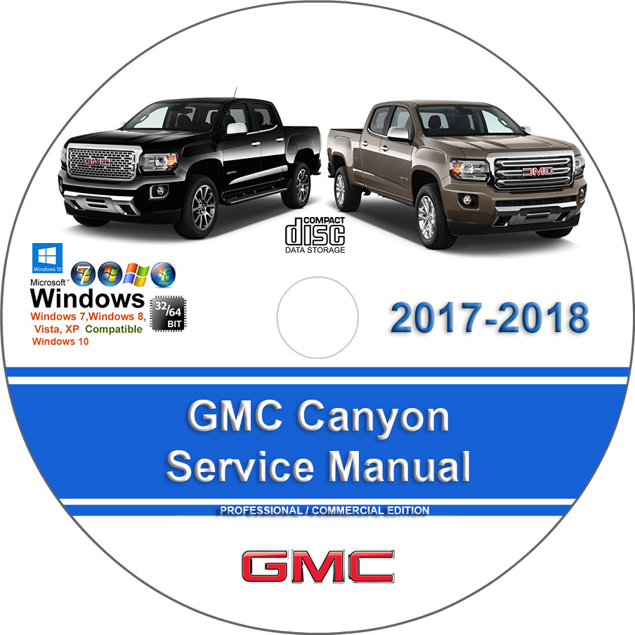
GMC Canyon 2017 2018 Factory Service Repair Manual + Wiring
$34.00 – $42.00Price range: $34.00 through $42.00
GMC Canyon 2017 2018 Factory Service Repair Manual + Wiring
You can download this or I can ship it to you.
Loaded with Hi Resolution illustrations, instructions, photos, and diagrams, complete to service and repair your GMC.
Pages: 11000+
GMC Canyon 2017 2018 Factory Service Repair Manual + Wiring
The Canyon by GMC is fair sized pickup truck that is offered in different lodge sizes and bed lengths. The base models are furnished with 16″ compound wheels, running lights, material/vinyl upholstery, controlled driver seat, tilting guiding wheel, stopping camera, every single fueled embellishment, 4.2″ touchscreen and essential sound framework. Alternatives and upper trim levels can include a bigger lodge and longer bed length, overhauled upholstery, Bluetooth/USB reconciliation, remote passage/start, antitheft framework, moving Wi-Fi, locking back differential, bigger wheels, foglamps, HD/satellite radio, rough terrain bundle, warmed/fueled side mirrors, impact alleviation framework, Bose sound framework, 8″ touchscreen comfort, GPS, and that’s only the tip of the iceberg. Controlling this truck is a 2.5-liter four-chamber motor that produces 200 pull and 191 pound-feet of torque.
Models Covered :
2017 Version Compatible with:
GMC Canyon 2017
GMC Canyon 2018
Manual Covers :
Accessories and Equipment:
Air Wind Noise
Bolted Exterior Body Panels and Closures
Bumpers and Fascia
Cellular, Entertainment, and Navigation
Cruise Control
Data Communications
Displays and Gauges
Exterior Trim
Fixed and Moveable Windows
Floor Coverings and Headlining
Frame and Underbody
Horns and Pedestrian Alerts
Immobilizer
Instrument Panel and Console Trim
Interior Trim and Paneling
Lighting
Mirrors
Object Detection and Pedestrian Protection
Paint and Coatings
Power Seats
Programming and Setup
Remote Functions
Seat Hardware, Trim, and Upholstery
Seat Heating and Cooling
Secondary and Configurable Customer Controls
Squeaks and Rattles
Theft Deterrent
Vehicle Access
Water leaks
Wipers and Washers
Wiring Systems and Power Management – Repair Instructions
Automatic Stop/ Start Disable:
Automatic Stop/ Start Disable
Brakes:
Antilock Brake System
Disc Brakes
Hydraulic Brakes
Park Brake
Trailer Brake Controls
Canadian Model Reference:
Canadian Model Reference
Common Specs and Procedure:
Common Specs and Procedure
Driveline and Axle:
Front Drive Axle
Propeller Shaft
Rear Drive Axle
Wheel Drive Shafts
DTC Index:
DTC Index
EGR Function Testing:
EGR Function Testing
Electrical:
12 V Starting and Charging
Power Outlets
Component Connector End Views – Index
Component Connector End Views – A7 To B63RR
Component Connector End Views – B65 To K9
Component Connector End Views – K111 To Q77J
Component Connector End Views – K20 LGZ To K109
Component Connector End Views – K9 To K20 LCV
Component Connector End Views – Q83A To X92
Door Component Views
Electrical Center Identification Views
Front of Vehicle Engine Compartment Component Views
Ground Views
Inline Harness Connector End Views – Index
Inline Harness Connector End Views – X100 To X108
Inline Harness Connector End Views – X109 To X202
Inline Harness Connector End Views – X203 To X800
Instrument Panel Center Console Component Views
Luggage Compartment Rear of Vehicle Component Views
Master Electrical Component List
Passenger Compartment Roof Component Views
Powertrain Component Views
Splice Pack Connector End Views
Wheels Vehicle Underbody Component Views
Description and Operation
Diagnostic Information and Procedures
Inline Harness Connector And Component Connector End Views – Miscellaneous
Schematic and Routing Diagrams
Special Tools and Equipment
Fastener Specifications
Emission:
Emission Applications
Emission Applications – Diesel
Control Abbreviations
Engine Performance:
2.5L (LCV) – Description and Operation
2.5L (LCV) – Diagnostic Information and Procedures
2.5L (LCV) – Repair Instructions
2.5L (LCV) – Schematic and Routing Diagrams – Engine Controls Schematics
2.5L (LCV) – Special Tools and Equipment
2.5L (LCV) – Specifications
2.8L (LWN) Diesel – Description and Operation – Accelerator Pedal Position System Description
2.8L (LWN) Diesel – Description and Operation
2.8L (LWN) Diesel – Diagnostic Information and Procedures
2.8L (LWN) Diesel – Introduction – Diesel Particulate Filter (DPF) System Description
2.8L (LWN) Diesel – Repair Instructions
2.8L (LWN) Diesel – Schematic and Routing Diagrams – Engine Controls Schematics
2.8L (LWN) Diesel – Special Tools and Equipment
2.8L (LWN) Diesel – Specifications
3.6L (LGZ) – Description and Operation
3.6L (LGZ) – Diagnostic Information and Procedures
3.6L (LGZ) – Repair Instructions
3.6L (LGZ) – Schematic and Routing Diagrams – Engine Controls Schematics
3.6L (LGZ) – Special Tools and Equipment – Special Tools
3.6L (LGZ) – Specifications
Firing Order & Cylinder Identification
Mode 6
Engine:
Cooling
2.5L (LCV)
2.8L (LWN) Diesel
3.6L (LGZ) – Component Locator
3.6L (LGZ) – Description and Operation
3.6L (LGZ) – Diagnostic Information and Procedures
3.6L (LGZ) – Repair Instructions – Off Vehicle
3.6L (LGZ) – Repair Instructions – On Vehicle
3.6L (LGZ) – Schematic and Routing Diagrams
3.6L (LGZ) – Special Tools and Equipment
3.6L (LGZ) – Specifications
Exhaust
Maintenance and Lubrication
General Information:
Anti-Lock Brake Safety Precautions
Clutch Trouble Shooting
Commonly Used Abbreviations
Dangers, Warnings, and Cautions
Drive Axle Noise Diagnosis
Electrostatic Discharge (ESD) Warning – Basic Information
Engine Displacement Conversion Table
Engine Overhaul Procedures
Engine Performance Diagnostic Routine Outline
Engine Performance Safety Precautions
English-Metric Conversion Chart
Gear Tooth Contact Patterns
General Cooling System Service
General Information
Manual Transmission Trouble Shooting
Parasitic Load Explanation & Test Procedures
State Emission Standards – Gasoline
State Emission Standards
Symptom Check List Worksheets
Trouble Shooting – Basic Procedures
TROUBLE SHOOTING
Using Wiring Diagrams
Diagnostic Information and Procedures
Specifications
Vibration Diagnosis and Correction
Waveforms – Injector Pattern Tutorial
Wheel Alignment Theory & Operation
HVAC:
Heating, Ventilation, and Air Conditioning
Automatic
Manual
Reminder Indicator Reset Procedures:
Reminder Indicator Reset Procedures
Restraints:
Seat Belts
Supplemental Restraints
Steering:
Power Steering
Steering Wheel and Column
Suspension:
Front Suspension
Wheel Alignment Specifications
Rear Suspension
Suspension General Diagnosis
Tire Pressure Monitoring
Tires and Wheels
Wheel Alignment
System Wiring Diagrams:
Wiring Diagrams
Tire Pressure Monitor Systems:
Tire Pressure Monitor Systems
Traction Control:
4WD and AWD
Transmission:
6L50 (MYB) – Component Locator
6L50 (MYB) – Description and Operation
6L50 (MYB) – Diagnostic Information and Procedures
6L50 (MYB) – Repair Instructions – Off Vehicle
6L50 (MYB) – Repair Instructions – On Vehicle
6L50 (MYB) – Schematic and Routing Diagrams
6L50 (MYB) – Special Tools and Equipment
6L50 (MYB) – Specifications
8L45 (M5T) – Component Locator
8L45 (M5T) – Description and Operation
8L45 (M5T) – Diagnostic Information and Procedures
8L45 (M5T) – Repair Instructions – Off Vehicle
8L45 (M5T) – Repair Instructions – On Vehicle
8L45 (M5T) – Schematic and Routing Diagrams
8L45 (M5T) – Special Tools and Equipment
8L45 (M5T) – Specifications
Clutch
Manual Transmission – Eaton 6-Speed (N8D)
Shift Lock Control
Transfer Case – MP 1622G (NQ7)
Transfer Case – MP 3025G (NQ6)
Cooling
Uniform Inspection and Communication Standards:
Brake Systems
Drive Train & Transmission Systems
Electrical Systems
Engine Performance And Maintenance
Exhaust Systems
Heating, Ventilation And Air Conditioning Systems
Routine Inspection Reference Guide
Steering & Suspension Systems
This manual is the same as the manual used by workshops. Service Manual contains detailed instructions and step by step diagrams for all workshop procedures.
Language: English
Format: PDF
COMPATIBLE WITH ALL WINDOWS & MAC COMPUTERS
(WINDOWS 10, WINDOWS 8, WINDOWS 11, ETC.)
Windows/Mac/Tablet/Phone Friendly
| Medium | USB Flash Drive, DVD, Download |
|---|
